|
Turning
Machines -
Lathe Construction
|
The five main parts of the lathe are: the bed, the headstock, the carriage, the
tailstock, and the gearbox. Below are illustrations of different lathes and
lathe parts. Study these parts and be ready to answer questions concerning their names and
locations.

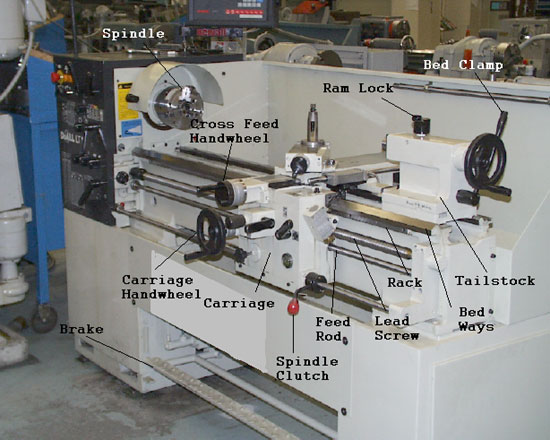
Figure 1 Engine lathe parts
Figure
1: Engine Lathe Part Descriptions |
| Spindle |
The spindle holds and drives the workpiece. |
| Cross Feed Handwheel |
The cross feed handwheel is used to manually position and/or hand
feed the compound rest in the X axis. |
| Carriage Handwheel |
The carriage handwheel is used to manually position and/or hand feed
the carriage in the longitudinal or Z axis. |
| Carriage |
The carriage houses the saddle, the cross slide, and the apron. The
main function of the carriage is to position the tool along the lathe bed. |
| Spindle Clutch Lever |
This lever controls the spindle’s rotation and direction. |
| Brake |
This type of spindle brake uses the foot pedal. The foot pedal type
of brake is found on many types of lathes. When the foot pedal is actuated, the spindle
will stop regardless of the position of the spindle clutch lever. |
| Feed Rod |
The feed rod transmits power from the headstock to the carriage for
feeding operations. |
| Lead Screw |
The lead screw transmits power from the headstock to the carriage
for screw thread cutting operations. On some lesser types of lathes the feed rod and the
lead screw are used for both the feed and the screw cutting power transmission. |
| Rack |
The rack or gear rack, as it is sometimes referred to, links with
the carriage handwheel to make longitudinal movement of the carriage possible. |
| Bed Ways |
The bed ways align the components of the lathe. The bed is the back
bone of the machine. |
| Tailstock |
The tailstock is used to support the right end of the work. The
tailstock is also used for tool-holding for machining operations, such as drilling,
reaming, and tapping. |
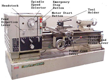
Figure 2 -
Lathe Parts Descriptions |
| Headstock |
The headstock houses the spindle and the components which drive the
spindle and the feed gears. |
| Spindle Speed Selector |
The spindle speed selector allows the operator to adjust the spindle
speed of the machine. |
| Emergency Stop Button |
The emergency stop button turns off the power to the machine. |
|

Figure 2 Lathe parts
|
| Motor Start Button |
The motor start button starts the electric drive motor for the
machine. The motor start button does not control the spindle; however, it does supply the
power. |
| Spindle Clutch and Brake Lever |
This lever controls the spindle rotation. Through the use of this
lever, the operator controls the spindle direction, spindle on, and spindle off. On some
machines, when the spindle is turned off, a magnetic spindle brake is applied. The other
type of spindle brake is the foot pedal. The foot pedal type of brake is found on many
other types of machines. |
|
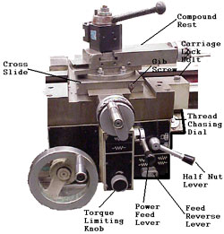
Figure
3 - Lathe Carriage Parts Descriptions |
| Power Feed Lever |
The power feed lever controls the automatic movement of the axes.
The two axes of movement associated with the lathe are the Z and X axes. The Z axis is the
longitudinal axis, while the X axis is the cross slide axis. |
| Tool Holder |
The tool holder holds the cutting tool. |
| Feed Direction Lever |
The feed direction lever or feed reverse lever controls the
direction of automatic feed on the lathe. |
| Half Nut Lever |
The half nut lever engages the carriage directly to the lead screw.
The half nut lever is used only for threading. The half nut lever will only engage when
the feed is set in the neutral position. |
|

Figure 3 Lathe carriage parts
|
| Thread Chasing Dial |
The thread chasing dial is used for threading. The thread chasing
dial works off the leadscrew and is used as a tracking device. The dial tells you when to
engage the half nut lever so the tool follows the same thread groove every time. |
| Cross Slide |
The cross slide allows for tool travel 90 degrees to the bed of the
lathe. The cross slide makes up the X axis of the machine. The X axis of the machine
controls the diameter of your work. |
| Compound Rest |
The compound rest is mounted on the cross slide and can be swiveled
to any angle. The compound is typically used for cutting chamfers or tapers, but must also
be used when cutting threads. The compound rest can only be fed by hand. There is no power
to the compound rest. |
| Carriage Lock Bolt |
The carriage lock bolt tightens the carriage to the bed of the machine. The carriage lock
is typically used during facing, grooving, or parting operations. |
| Gib Screw |
The gib screw is used to take up clearance between the gib and the
dovetail. Clearance between the gib and the dovetail will occur normally due to
wear. |
|
Top 
|


