
Sterling Drill Grinder
| Using a drill grinding machine is the quickest and most
accurate method of sharpening drills. There are many different types of
drill grinding machines used in the machining industry today. This unit
will concentrate on the Sterling drill grinding machine (Figure 1). |
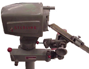
Figure 1 Sterling Drill Grinder |
The Sterling drill grinding machine will sharpen drills from
1/8 inch through
2-1/2 inches in diameter. The Sterling drill grinder uses
a V-block method of holding the drill (Figure 2). The V-block is simple,
positive, and eliminates the need for collets and chucks. Locating it on the
drill stop blade helps to take the guess work out of drill grinding
(Figure 2). |
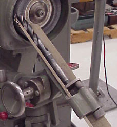
Figure 2
|
Drill Grinding Procedure
|
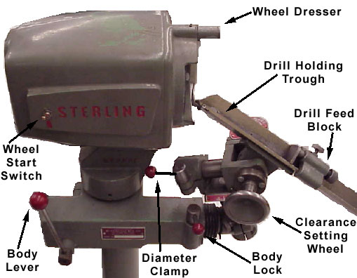
Figure 3 The main components of the
sterling drill grinder
|
Before we can begin learning how to grind the drill using the
Sterling drill grinder, we must first learn the main parts of the grinder
(Figure 3). |
Wheel
Dresser
| A clean, free cutting wheel is important for accurate, cool
grinding. To operate the built-in diamond wheel dresser, first start by
loosening the knurled lock nut on the dresser and back out the diamond
until the diamond clears the face of the wheel (Figure 4). |
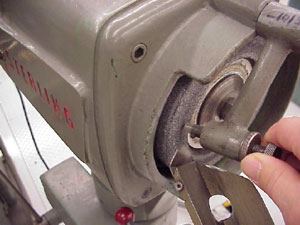
Figure 4
|
Swing the dresser in front of the wheel and feed in the diamond point until
it contacts the wheel. Swing the dresser up out of the way of the wheel. Snug up
the lock nut. Start the wheel and swing the dresser back and forth across the
wheel. Feed the diamond in and repeat until the wheel face is flat and clean.
Setting Up to Grind a Given Diameter
Drill
| To set the holder for the proper size drill, we must first release the
diameter clamp (Figure 3)and move the entire holding unit in or out until
the pointer of the drill diameter scale (Figure 5) is the same as the
drill size that we want to grind. |
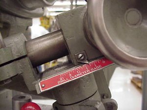
Figure 5
|
|
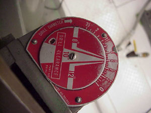
Figure 6
|
Lock the clamp back up. Turn the clearance setting wheel (Figure 3) until
the proper pointer on the drill clearance gage (Figure 6) corresponds with
the diameter of the drill to be ground. |
| To provide clearance for setup, move the drill holding unit out of the
way by releasing the body lock and pulling the body lever forward. Provide
1/32 inch clearance between the wheel and the drill stop located at the
end of the drill holder trough (Figure 7). |
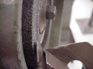
Figure 7
|
Swing the drill holding unit carefully to be sure that the drill stop clears
the wheel. If the wheel stop doesn’t clear the wheel, move the drill holding
unit back another 1/32 inches. Lock the body clamp back up.
Grinding the Drill
| Release the knurled lock screw on the drill feed block (Figure 8). Lay
the drill to be ground in the drill holding "V" trough. |
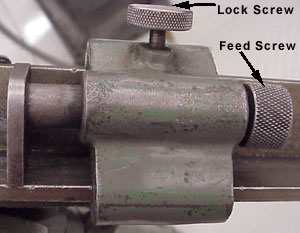
Figure 8
|
| Slide the drill feed block up until the drill point clears the wheel by
1/32 of an inch. Locate the drill flute lip against the drill stop blade
(Figure 9). Turn on the drill motor using the wheel start switch (Figure
3). |
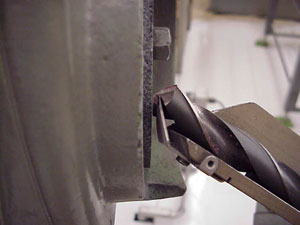
Figure 9
|
| Hold the drill using your thumb and index finger through the hole in the
trough (Figure 10). |
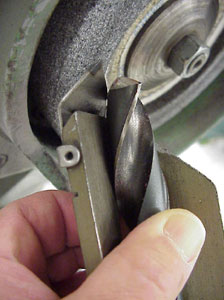
Figure 10
|
|
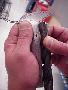
Figure 11
|
Swing the drill holding unit through its full arc and feed the drill up
to the wheel using the drill feed screw until the drill makes light
contact with the wheel. Grind a small amount off of the lip and turn the
drill over and grind an equal amount off of the opposite lip using the
same method. Grind the lips alternately until the proper drill point is
achieved. Check the lip lengths and drill point angle with a drill lip
gage (Figure 11). |
|