Tools used in drilling operations represent nearly 25% of all the tools being used in the world. There are those operations that are strictly drilling operations, but we also use drilling machines to perform other operations such as reaming, tapping, countersinking and counterboring. The rules and principles of cutting speeds and RPM calculations apply to all of the operations being performed on drilling machines. An example of this would be reaming. Reaming is done at half the speed and twice the feed as drilling. This rule still applies on the drill press as it does on the milling machine or the lathe. Pay very close attention to the information introduced in this unit and other units dealing with cutting speeds because cutting speeds have the greatest impact on tool life.
Cutting speed is the speed at the outside edge of the tool as it is cutting. This is also known as surface speed. Surface speed, surface footage, and surface area are all directly related. If two tools of different sizes are turning at the same revolutions per minute (RPM), the larger tool has a greater surface speed. Surface speed is measured in surface feet per minute (SFPM). All cutting tools work on the surface footage principle. Cutting speeds depend primarily on the kind of material you are cutting and the kind of cutting tool you are using. The hardness of the work material has a great deal to do with the recommended cutting speed. The harder the work material, the slower the cutting speed. The softer the work material, the faster the recommended cutting speed (Figure 1).
The hardness of the cutting tool material will also have a great deal to do with the recommended cutting speed. The harder the drill, the faster the cutting speed (Figure 2). The softer the drill, the slower the recommended cutting speed.
The three factors, cutting speed, feedrate and depth of cut, are known as cutting conditions. Cutting conditions are determined by the machinability rating of the material. Machinability is the comparing of materials on their ability to be machined. From machinability ratings we can derive recommended cutting speeds. Recommended cutting speeds are given in charts. These charts can be found in the Machinery’s Handbook, textbook, or a chart given to you by your tool salesperson. In Table 3 you will find a typical recommended cutting speed chart for drilling. Table 3 Recommended Cutting Speeds for Drilling with
High-Speed Steel Drills
The spindle speed must be set so that the tool will be operating at the correct cutting speed. To set the proper spindle speed, we need to calculate the proper revolution per minute or RPM setting. We stated earlier that cutting speed or surface speed would change with the size of the tool. So to keep the surface speed the same for each size tool, we must use a formula, which includes the size of the tool, to calculate the proper RPM to maintain the proper surface footage.
The RPM setting for drilling depends on the cutting speed of the material and the size of the drill bit. The RPM setting will change with the size of the bit. As the drill bit gets smaller, the RPM must increase to maintain the recommended surface footage. Take the case of the wheel. Think of the drill bit as a wheel and the cutting speed as a distance. A larger wheel (drill bit) will need to turn less revolutions to cover the same distance in the same amount of time than a smaller wheel (drill bit). Therefore, to maintain the recommended cutting speed, larger drills must be run at slower speeds than smaller drills. The drill press must be set so that the drill bit will be operating at the proper surface speed. Spindle speed settings on the drill press are done in RPMs. To calculate the proper RPM for the tool, we must use the following formula: Cutting speed (CS) X 4 This simplified version of the RPM formula is the most common formula used in machine shops. This RPM formula can be used for other machining operations as well. Let's put this formula to work in calculating the RPM for the drilling example below. Use the recommended cutting speed charts in Table 3. A 0.50 drill is being used to drill a piece of 1018 steel with a brinnel hardness of 200. Calculate the RPM setting to perform this drilling operation.
Although you have calculated the RPM, remember that this is only a recommendation. Some judgment must be made in selecting the actual R.P.M. setting to use. There are always outside factors that must go into deciding on the proper speed and feed to use. Ask yourself these questions before deciding on an R.P.M. setting. How sturdy is my setup? Go slower for setups, which lack a great deal of rigidity. Am I using coolant? You may be able to use a faster speed if you are using flood coolant. How deep am I drilling? If you’re drilling a deep hole, there is no place for the heat to go. You may have to slow the RPM down for deep whole drilling. The greatest indicator of proper and improper cutting speed is the color of the chip. When using a high-speed steel drill bit, the chips should never be turning brown or blue. Straw-colored chips indicate that you are on the maximum edge of the cutting speed for your cutting conditions. When using carbide, chip colors can range from amber to blue, but never black. A dark purple color will indicate that you are on the maximum edge of your cutting conditions. Carbide cutting tools are covered in much greater detail in another section of your learning materials. Let’s try some more examples. A 1.00-inch, high-speed steel (HSS) drill is being used on a piece of 1045 steel with a brinnel hardness of 300. Calculate the RPM setting to perform this cutting operation.
A 3/4-inch (HSS) drill is used on a piece of (leaded) 11L17 steel with a brinnel hardness of 100. Calculate the RPM setting to perform this drilling operation.
The drill press RPM setting for reaming depends on the cutting speed of the material and the size of the ream. The RPM setting will change with the size of the ream. As the ream gets smaller, the RPM must increase to maintain the recommended surface footage. Although you will find specific cutting speeds for reaming, a simple rule of half the speed will work for most reaming operations. Using half the spindle speed you calculated for the drilling operation is a commonly accepted method for determining the reaming speed in most machine shops. Let’s try an example. A high speed steel "G" drill is being used prior to reaming a 3/8 hole on a piece of 1095 steel with a brinnel hardness of 300. Calculate the RPM setting to perform the drilling and reaming operations.
Half the speed for reaming would be = 432 / 2 = 216 RPM for reaming.
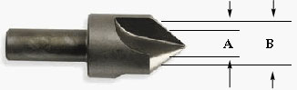
The drill press RPM setting for countersinking and counterboring also depends on the cutting speed of the material and the size of the tool. The RPM setting will change with the size of the tool. As the cutting tool gets smaller, the RPM must increase to maintain the recommended surface footage. Although you will find specific cutting speeds for countersinking and counterboring, a simple rule of 1/3 the speed of a drill of the same size will work for most countersinking and counterboring operations. The RPM for a counterbore would be fairly simple to calculate using the 1/3 method, but calculating the RPM for a countersink brings about a different set of circumstances. The countersink is tapered (Figure 4).
Let’s try an example. Let’s calculate the RPM for the countersink in Figure 5. The material is 1045 steel with a brinnel hardness (bhn) of 200.
One-third the speed for countersinking would be = 789/ 3 = 263 RPM.
A center drill or combination drill and countersink (Figure 6) is used for spotting holes in workpieces or for making center holes for turning work. Center drills, as you can see from the illustration, are short and sturdy and will not bend or flex under pressure. When calculating the proper RPM for using a center drill, use the diameter of the pilot for your calculations. Center drills will break if they are run too slowly. Using the smaller diameter of the center drill will assure that the RPM setting is sufficient. If you find that the drill chatters as you reach the proper depth, slightly decrease the RPM setting.
Let’s try an example. Lets calculate the RPM for the center drilling 1018 steel with brinnel hardness (bhn) of 100. A #4 center drill with a pilot drill diameter of 1/8 inch will be used.
Selecting the best RPM for power tapping can be very complicated. There are many variables that must be taken into consideration when selecting the best spindle speed for machine tapping. Among the variables are:
The RPM formula for tapping is no different from the other formula we have been using, but the consideration mentioned for tapping must be made before we actually do any power tapping. Until you know how the tap will operate under your conditions, start with 1/3 to 1/2 the calculated RPM and gradually increase the RPM to the capacity of the conditions. A table of recommended cutting speeds for threading is included in Table 7. Table 7 Cutting Speeds for Machine Tapping
Let’s try an example. Let’s calculate the RPM for tapping a 1/2-13 UNC hole. The material is 1018 steel with a brinnel hardness (bhn) of 100.
|