I am looking for: Learn arrow down
I am looking for:
Categories
Categories
Identifying Engineering Notation
The learner will represent very large and very small numbers in engineering notation.
By Ron Wallberg
Basic Types of Dimensioning Used in Engineering Drawings
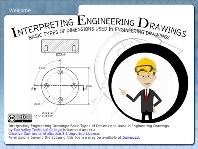
Learners examine the basic types of dimensioning including unidirectional and aligned systems, and linear, aligned, angled, arrowless, chain, datum, chart, tabular, radius, diameter, typical, and reference dimensions.
By Kelly Curran Glenn Sokolowski
Basic Symbols Used in Engineering Drawings
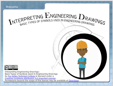
Learners examine the drawing symbols used for counterbore, countersink, spotface, radius, diameter, and depth. In the quiz that completes the activity, they associate these symbols with machining applications.
By Kelly Curran Glenn Sokolowski
Basic Elements of Dimensions Used in Engineering Drawings
In this interactive object, students explore the basic elements and common terms associated with dimensions and leaders. A quiz completes the activity.
Interpreting Engineering Drawings: Sheet Sizes

In this animated and interactive object, learners view American National Standard and International Standard sheet sizes. A quiz completes the activity.
Engineering Design Process

Try matching the 8 steps of the Engineering Design Process. After you finish....try to beat your score!
Engineering Culture's Week 4-6

Engineering Culture's Week 10-12
Engineering L3

Thread Specifications
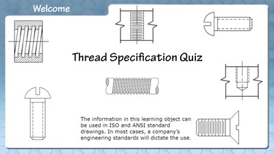
In this interactive object, learners examine standard and metric thread specifications used in engineering drawings. In a brief quiz, they identify various internal and external thread representations.
Pictorial Drawings
Learners examine pictorial drawings used in engineering including sectioned and exploded drawings. A sketching quiz is provided to help the learner create simple pictorial sketches by using orthographic views and an isometric template.
Sectional Views
In this interactive object, learners examine sectional views used in engineering drawings. The sections shown are full, half, offset, aligned, revolved, and broken-out. Learners match drawings of sectional views with the names of the views.
Basic Types of Lines Used in Engineering Drawings
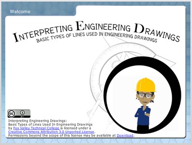
In this highly interactive object, learners associate basic line types and terms with engineering drawing geometry. A quiz completes the activity.
By Kelly Curran Glenn Sokolowski
Interpreting Engineering Drawings: Title and Revision Blocks (Screencast)
Learners examine the information on a title block and answer questions about that information in an interactive quiz.
Interpreting Engineering Drawings: Common Abbreviations
In this interactive object, learners read the common abbreviations used in engineering drawings and then test their knowledge in three short exercises.