I am looking for: Learn arrow down
I am looking for:
Categories
Categories
Construction of the Cell Membrane
In this learning activity you'll study the structure of the cell membrane and construct it using the correct molecules.
By Becky Polk-Pohlman Barbara Liang
The Cell Membrane and Nanotechnology
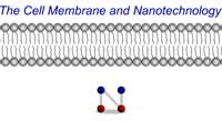
In this animated activity, learners examine nanotechnology applications that are based on cell membrane structure and function.
Transfer Functions: The RC High Pass Filter
Learners read how the transfer function for a RC high pass filter is developed. The transfer function is used in Excel to graph the Vout. The circuit is also simulated in Electronic WorkBench and the resulting Bode plot is compared to the graph from Excel.
Transfer Functions: The RC Low Pass Filter

Students read how the transfer function for a RC low pass filter is developed. The transfer function is used in Excel to graph the Vout. The circuit is also simulated in Electronic WorkBench and the resulting Bode plot is compared to the graph from Excel.
Transfer Functions: The RL Low Pass Filter

Learners read how the transfer function for a RC low pass filter is developed. The transfer function is used in Excel to graph the Vout. The circuit is also simulated in Electronic WorkBench and the resulting Bode plot is compared to the graph from Excel.
The Function Generator: Frequency Control
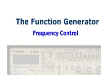
Learners read how to use the knobs and the output terminals of a Wavetek Model 25 function generator to obtain a waveform at a desired frequency.
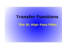
Transfer Functions: The RL High Pass Filter With Bode Plot
Learners read how the transfer function for a RL high pass filter is developed. The transfer function is used in Excel to graph the Vout. The circuit is also simulated in Electronic WorkBench, and the resulting Bode plot is compared to the graph from Excel.
Construction of the Cell Membrane (Video)
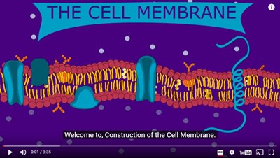
In this video you'll study the structure of the cell membrane and construct it using the correct molecules.
The Function Generator
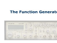
Students read a description of the function generator and view a graphic that labels its parts.
Veterinary Muscle Function Drugs
In this interactive object, learners sort veterinary muscle function medications into categories.
By Laura Lien
The TI-83 Plus Calculator: Using the Arctangent Function
Learners read how to use the arctangent function to calculate the theta of an angle. The proper keystrokes are displayed.
The TI-86 Scientific Calculator: Using the Log Function
This primer introduces the student to the correct method of using the log function on a TI-86 calculator.
The TI-83 Plus Calculator: Using the Exponent Function
This primer introduces the student to the proper use of the "EE" function to perform calculations on very large or very small numbers.
The TI-86 Scientific Calculator: Using the Arctangent Function
This primer introduces the student to the correct method of using the arctangent function on a TI-86 calculator.
The Brain - Anatomy and Function
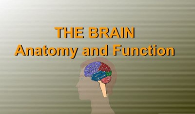
Learners review and reinforce their knowledge of brain anatomy and function in this learning activity.
The Counter-Reset Function
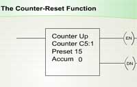
Learners examine the counter-reset function of a programmable controller and how it is used.
The TI-86 Scientific Calculator: Using the Exponent Function
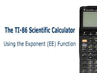
This primer introduces the student to the proper use of the exponent (EE) function on a TI-86 calculator.
Identifying Hand Tools by Function

Transfer Functions: The RL High Pass Filter (Screencast)
Learners read how the RL high pass filter is developed. The transfer function is used in Excel to graph the Vout. The circuit is also simulated in Electronic WorkBench and the resulting Bode plot is compared to the graph from Excel.
The Function Generator: Voltage Control
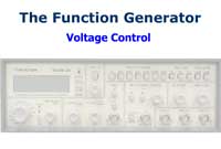
Learners read a description of the knob controls, pushbuttons and output terminals on the Wavetek Model 25 signal generator.