I am looking for: Learn arrow down
I am looking for:
Categories
Categories
Using Blueprints to Troubleshoot a Defective Compressor Motor

In this simulation activity, an electrician troubleshoots a defective compressor motor that will not start. To find the problem, the learner selects the appropriate blueprints that must be referred to while performing the troubleshooting steps. Then safety protocols will be followed, such as making lockout-tag out installations and donning PPE items before taking measurements with a multimeter to locate the faulty component.
Using Blueprints to Troubleshoot a Defective Water Pump

In this simulation activity, an electrician troubleshoots a defective water pump that will not start. To find the problem, the learner selects the appropriate blueprints that must be referred to while performing the troubleshooting steps. Then safety protocols will be followed, such as making lockout-tag out installations and donning PPE items before taking measurements with a multimeter to locate the faulty component.
Analyze a Part Drawing
In this interactive object, learners answer 25 questions regarding part or assembly drawings. The basic areas of blueprint reading are covered.
Print Reading: An Alphabet of Lines in Print Reading
In this animated activity, learners read about the types of lines found on blueprints. A quiz completes the activity.
By Kelly Curran
Troubleshooting a Three Phase Motor that is Overheating

In this simulation activity, an electrician will troubleshoot an AC motor that is overheating. Before accessing blueprints and then using a multimeter to find the fault, the learner will follow safety protocols by following lock-out tag-out procedures and then suit up with appropriate (PPE) personal protection equipment.
Orthographic Sketching
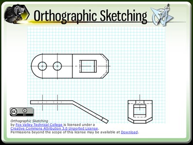
The learner will understand how to view an object for interpretation in the standard orthographic format and then accurately sketch three orthographic views using 3rd angle projection.
GD&T: Geometric Characteristic Symbols
In this interactive object, learners test their knowledge of 14 geometric tolerance control symbols.
Thread Specifications
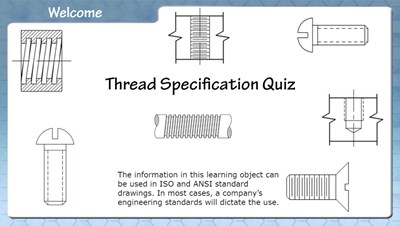
In this interactive object, learners examine standard and metric thread specifications used in engineering drawings. In a brief quiz, they identify various internal and external thread representations.
Parts Make an Assembly
Learners examine the relationship of individual parts in an assembly drawing. Assembly drawing notes, fabricated and purchased parts, and sectional views are explained briefly.
Print Reading: Holder
Learners test their ability to visualize a holder in this interactive exercise that features animated pictorial views.
By Kelly Curran
Interpreting Engineering Drawings: Common Abbreviations
In this interactive object, learners read the common abbreviations used in engineering drawings and then test their knowledge in three short exercises.
Print Reading: Angled Mount
Learners test their ability to visualize an angled mount in this interactive exercise that features animated pictorial views.
By Kelly Curran
Pictorial Drawings
Learners examine pictorial drawings used in engineering including sectioned and exploded drawings. A sketching quiz is provided to help the learner create simple pictorial sketches by using orthographic views and an isometric template.
Sectional Views
In this interactive object, learners examine sectional views used in engineering drawings. The sections shown are full, half, offset, aligned, revolved, and broken-out. Learners match drawings of sectional views with the names of the views.
Print Reading: Mounting Wedge
Learners test their ability to visualize a mounting wedge in this interactive exercise that features animated pictorial views.
By Kelly Curran
Brain Exercise: Visualization #2
In this interactive object, learners practice their 3D visualization skills by identifying the correct isometric view of an object.
Brain Exercise: Visualization #3
Learners develop 3D visualization skills by examining front, side, and top orthographic views of objects. Using this information, students select the corresponding isometric view of each object.
Title Block Tolerances
Learners examine the use of the tolerances displayed in a title block by calculating the minimum and maximum allowable size of a fabricated part. In a brief quiz, students determine whether a part is usable or should be scrapped.
Basic Types of Lines Used in Engineering Drawings
In this highly interactive object, learners associate basic line types and terms with engineering drawing geometry. A quiz completes the activity.
By Kelly Curran Glenn Sokolowski
Surface Texture Symbols

Learners examine the symbols and values that control surface roughness, waviness, and lay. A brief quiz completes the object.