I am looking for: Learn arrow down
I am looking for:
Categories
Categories
The Firing Circuit of a DC Drive
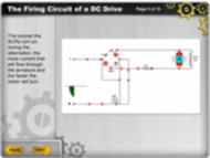
In this animated activity, learners examine the firing circuits in a DC variable speed drive. The circuits cause the current flow through the armature and rpm to vary. This activity has audio content.
High-Low Speed Drive Adjustments

Learners examine the circuitry in a DC variable speed drive that prevents the motor from running at 0 rpm or at maximum speed under certain conditions.
The Cycloidal Gear Drive
The learner will gain an understanding of the inner workings of the cycloidal gear drive while watching a video and listening to an explanation of its features.
By cebery
The Planetary Gear Drive

The learner will understand the design of a planetary gear drive and its advantages and disadvantages.
By cebery
Fan-Out: Determining the Load Drive Capability of an IC

Students follow steps to determine the number of inputs that can be driven by a specific IC. A sample problem is given.
Volts per Hertz Ratio in AC Drives
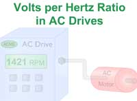
Learners view an animated explanation of why an adjustment of the output voltage by an AC drive is required to maintain a constant torque as the frequency is varied.
Secure Data Erasure

In this simulation, you’ll learn to differentiate between basic deletion and secure erasure to protect sensitive information.
By Baeten
Wireless Hardware

Learners consider the most common types of electromagnetic waves and the kinds of hardware used in a wireless network. A short quiz completes the activity.
The IR Comp Network
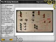
In this animated activity, learners examine the circuitry in a DC variable speed drive that keeps the motor running at a constant speed as the load varies.
Calculating Belt Length (Screencast)

In this screencast, learners follow steps to determine the proper starting belt length for a timing, flat, or v-belt drive.
Graphical BJT/JFET Transistor Biasing
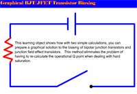
Learners use two calculations to prepare a graphical solution to the biasing of bipolar junction transistors and junction field effect transistors. This method eliminates the problem of having to re-calculate the operational Q point when dealing with hard saturation.
By Roger Brown
Modify Delivery Route
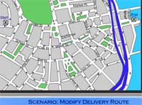
In this scenario, learners take the role of a delivery driver who must find a new travel route after the Interstate is closed to trucks. “Drivers” listen to traffic reports and write directions for a new route. This activity has audio content.
By Rosie Bunnow
Volts Per Hertz Ratio
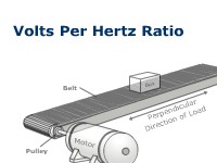
In this animated and interactive object, learners examine why the voltage produced by an AC drive must be increased when its frequency is increased due to inductive reactance.
Applying the Motor Voltage
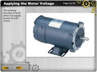
In this animated lesson, learners examine the rectifier circuitry in a DC variable speed drive that supplies the voltages to the field coil and armature.
Acceleration and Deceleration Adjustments

In this animated activity, learners examine the circuitry in a DC variable speed drive that causes the motor to accelerate or decelerate at slow rates. This learning object has audio content.
The Current Limiting Circuit

Learners examine the circuitry in a DC variable speed drive that protects the rectifier diodes and motor windings from being damaged due to excessive current.
BCD-to-Seven Segment Decoder
Learners will understand how binary-coded decimal information is decoded and used to drive a seven-segment display.
By Terry Bartelt Terry Fleischman
Setting Up a Wire Feeder for GMAW

In this animated and interactive object, learners follow steps that begin with choosing the correct drive roll and include feeding the electrode wire from the spool to the welding gun.
By Dave Hoffman
Stop-Button Wiring to a PLC

Learners consider the correct type of pushbutton to use as a Stop button, the way the Stop button should be hard wired, and the PLC input instruction to use. This animated object includes a short quiz. It is recommended that learners review the learning object “The PLC Examine-Off Instruction” before beginning this object.
Motor Speed Control
Learners examine the speed control circuits in a DC variable speed drive that cause the RPM of a motor to vary. This activity has audio content.