I am looking for: Learn arrow down
I am looking for:
Categories
Categories
The TI-86 Scientific Calculator: Using the Log Function
This primer introduces the student to the correct method of using the log function on a TI-86 calculator.
The TI-83 Plus Calculator: Using the LOG Function
Logic Probes
In this animated activity, learners examine the fundamental operation of a logic probe that is used to detect logic signals in a digital circuit.
Logic State Signals
In this learning activity you'll identify the voltage levels produced or recognized by digital logic devices as valid or invalid logic state signals.
Logic Probe Troubleshooting
In this animated object, learners follow a process for troubleshooting digital integrated circuits on a printed circuit board using a logic probe.
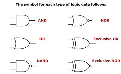
Logic Symbols (Screencast)
Logical Reasoning in Speeches (Screencast)
In this learning activity you'll be introduced to the eight most common logical fallacies commonly used in persuasive speeches.
Logical Reasoning in Speeches -"Either/Or" Fallacy
Logical Reasoning in Speeches - Research
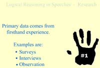
In this learning activity you'll explore the differences between primary and secondary research.
Logical Reasoning in Speeches - Slippery Slope
Logical Reasoning in Speeches - Red Herring
In this learning activity you'll be introduced to the Red Herring fallacy.
Logical Reasoning in Speeches - Ad Populum
In this learning activity you'll be introduced to the Ad Populum fallacy.
Logical Reasoning in Speeches - Ad Hominem
In this learning activity you'll be introduced to the Ad Hominem fallacy.
Logical Reasoning in Speeches - Ad Absurdum
In this learning activity you'll be introduced to the Ad Absurdum fallacy.
Logical Reasoning in Speeches - Post hoc, Ergo Propter hoc
In this learning activity you'll be introduced to the Post hoc, Ergo Propter hoc fallacy.
Logical Reasoning in Speeches - Ad Verecundiam
In this learning activity you'll be introduced to the Ad Verecundia fallacy.
Logic State Indicators
Instructions on how to interpret state indicator symbols for input and output terminals of digital devices is presented.
Routers: Logical Addresses
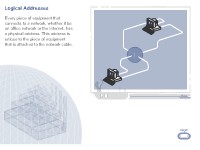
In this learning activity you'll examine how logical addresses work. The IP address is the logical address assigned to a connection by the ISP or network administrator.
By Joseph Wetzel Jeff Sonnleitner
Equivalent Gates/Ladder Logic Circuits
Learners will identify ladder logic diagrams and the logic functions they perform.
By Terry Bartelt Terry Fleischman
Tracing Logic Circuit Signals
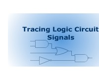
Learners follow steps to trace logic signals from the inputs of several interconnecting logic gates to one output.