I am looking for: Learn arrow down
I am looking for:
Categories
Categories
Vector Diagram for a Parallel RC Circuit
Learners read about the vector diagram for a parallel RC circuit. This animated lesson presents information on current flow through each branch, total current, and phase angle.
Vector Diagram for a Series RL Circuit
Learners view a vector diagram for a series RL circuit. Information on the voltage across each component, the total voltage, and the phase angle is included.
Vector Diagram for a Parallel RL Circuit
Learners read about the vector diagram for a parallel RL circuit. This animated lesson presents information on current flow through each branch, total current, and phase angle.
Vector Diagram for a Series RC Circuit
Learners view a vector diagram for a series RC circuit and read information concerning the voltage across each component, the total voltage, and the phase angle.
Rotating Vector Representation of the Sine Function
The learner will be able to represent steady-state AC sinusoidal signals using phasors, which will lead to a simplified technique of analyzing AC circuits in a very similar way that we analyze DC circuits.
Oscilloscope Phase Shift Measurements (Screencast)
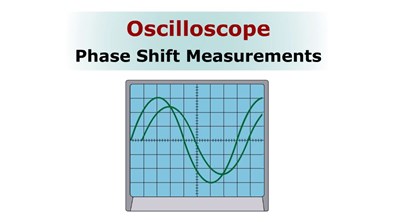
In this animated lesson, learners follow the steps required to read the phase shift difference in degrees between two AC waveforms.
Statics: Scalar vs. Vector
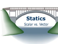
Learners read an introduction of scalar quantity and vector quantity and force. Examples are given.
Phase Diagrams
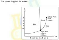
Learners examine phase diagrams that show the phases of solid, liquid, and gas as well as the triple point and critical point.
By Debbie McClinton Dr. Miriam Douglass Dr. Martin McClinton
Three Phase Wye Transformer Calculations
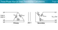
In this interactive object, learners follow steps to find phase voltages in a partial three-phase power distribution circuit.
Determining a Business Cycle Phase

In this learning activity you'll plot GDP data on a graph and determine a phase of the business cycle.
Parallel RC Circuit Vector and Circuit Analyzer
Learners alter circuit variables and view how these changes affect circuit voltage, current, reactance, impedance, and phase angle.
Excel: Rectangular to Polar Conversion for the Phase Angle in Radians
The conversion from rectangular to polar mode phase angle in radians is demonstrated in Excel.
Series RL Circuit Vector and Circuit Analyzer
Learners alter circuit variables and view how these changes affect circuit voltage, current, reactance, impedance, and phase angle.
Series RC Circuit Vector and Circuit Analyzer
In this teaching and learning aid, the user can alter circuit variables and view how these changes affect circuit voltage, current, reactance, impedance, and phase angle.
Parallel RL Circuit Vector and Circuit Analyzer
Learners alter circuit variables and view how these changes affect circuit voltage, current, reactance, impedance, and phase angle.
Phase-Splitting of Single-Phase Motors
The learner will understand the two methods used to create a phase shift in current between two windings.
By Terry Bartelt Terry Fleischman
Vectors in Polar Form

In this learning activity you'll place given vectors in correct positions on the Cartesian coordinate system.
Phase Relationships Between Line-Neutral and Line-Line Voltages
Learners view a demonstration showing that line-neutral voltages and line-line voltages are not in-phase with each other, but have a definite 30-degree relationship.
By Michael Gradinjan Terry Fleischman
Phase Transitions
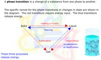
Learners examine how melting, vaporization, and sublimation require energy input while freezing and condensation release energy.
By Debbie McClinton Dr. Miriam Douglass Dr. Martin McClinton
Selecting a Proper Single Phase Transformer
Students follow the steps that are required to select a transformer with the proper ratings. Voltage, frequency, current, and KVA are considered.