I am looking for: Learn arrow down
I am looking for:
Wisc-Online
Categories
WTCSCategories
Categories
Timing Diagrams (Screencast)
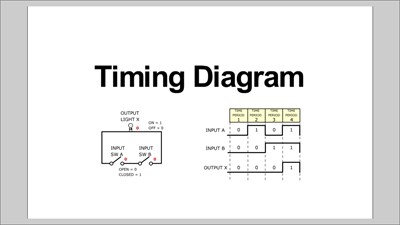
The explanation and use of timing diagrams used in digital electronics to graphically show the operation of various circuits are given.
The Timing Functions of Optical Sensors
In this animated object, learners examine the switch settings for the on-delay, off-delay, and one-shot timing functions of an optical sensor. A brief quiz completes the activity.
Calculating Belt Length (Screencast)
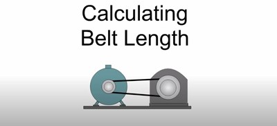
In this screencast, learners follow steps to determine the proper starting belt length for a timing, flat, or v-belt drive.
Propagation Delay
Learners examine the concept of propagation delay within a TTL logic gate. The concept is explained with the use of timing diagrams and sample calculations.