I am looking for: Learn arrow down
I am looking for:
Categories
Categories
How to Read a Caliper
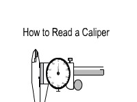
In this interactive object, learners review how to read a caliper. They then test their skills with eight practice questions.
Basic Types of Lines Used in Engineering Drawings
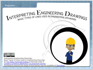
In this highly interactive object, learners associate basic line types and terms with engineering drawing geometry. A quiz completes the activity.
By Kelly Curran Glenn Sokolowski
Brain Exercise: Visualization #1
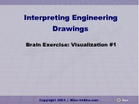
In this interactive object, learners practice their 3D visualization skills by identifying the correct isometric view of an object. Front, side, and top orthographic views are shown.
Orthographic Projection #1
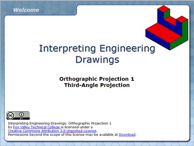
In this interactive and animated object, learners examine orthographic projection and the Glass Box Theory. Front, side, and top view development is demonstrated with pictorial views of each object to help develop 2D to 3D visualization skills.
Reading a Micrometer
Basic Symbols Used in Engineering Drawings
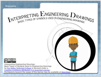
Learners examine the drawing symbols used for counterbore, countersink, spotface, radius, diameter, and depth. In the quiz that completes the activity, they associate these symbols with machining applications.
By Kelly Curran Glenn Sokolowski
Basic Types of Dimensioning Used in Engineering Drawings
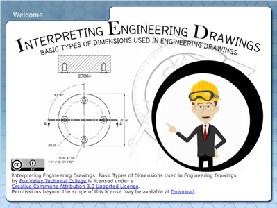
Learners examine the basic types of dimensioning including unidirectional and aligned systems, and linear, aligned, angled, arrowless, chain, datum, chart, tabular, radius, diameter, typical, and reference dimensions.
By Kelly Curran Glenn Sokolowski
Print Reading: An Alphabet of Lines in Print Reading
In this animated activity, learners read about the types of lines found on blueprints. A quiz completes the activity.
By Kelly Curran
Brain Exercise: Visualization #2
In this interactive object, learners practice their 3D visualization skills by identifying the correct isometric view of an object.
Brain Exercise: Visualization #3
Learners develop 3D visualization skills by examining front, side, and top orthographic views of objects. Using this information, students select the corresponding isometric view of each object.
The Dial Caliper
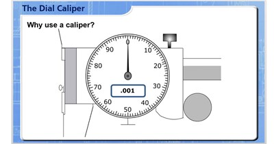
Learners review guidelines for the proper use of a dial caliper. Illustrations appear throughout the learning object.
Basic Elements of Dimensions Used in Engineering Drawings
In this interactive object, students explore the basic elements and common terms associated with dimensions and leaders. A quiz completes the activity.
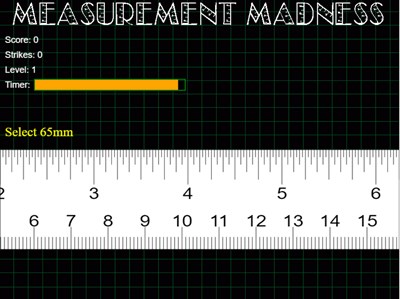
Measurement Madness
Sectional Views
In this interactive object, learners examine sectional views used in engineering drawings. The sections shown are full, half, offset, aligned, revolved, and broken-out. Learners match drawings of sectional views with the names of the views.
Sine Bar
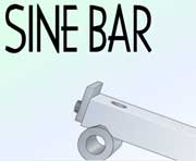
In this learning activity you'll examine how a sine bar is used to measure angles.
Analyze a Part Drawing
In this interactive object, learners answer 25 questions regarding part or assembly drawings. The basic areas of blueprint reading are covered.
Pictorial Drawings
Learners examine pictorial drawings used in engineering including sectioned and exploded drawings. A sketching quiz is provided to help the learner create simple pictorial sketches by using orthographic views and an isometric template.
Dial Caliper: Measurements Review

GD&T: Geometric Characteristic Symbols
In this interactive object, learners test their knowledge of 14 geometric tolerance control symbols.