I am looking for: Learn arrow down
I am looking for:
Categories
Categories
Determining a Business Cycle Phase
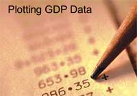
In this learning activity you'll plot GDP data on a graph and determine a phase of the business cycle.
Transfer Functions: The RL High Pass Filter With Bode Plot

Learners read how the transfer function for a RL high pass filter is developed. The transfer function is used in Excel to graph the Vout. The circuit is also simulated in Electronic WorkBench, and the resulting Bode plot is compared to the graph from Excel.
Reading and Interpreting Bar Graphs

In this learning activity you'll identify the various parts of a bar graph, read and interpret its data, and calculate the data to solve various application problems.
Database Data Types
In this activity, you'll learn about the different data types associated with databases.
By jamiecchavez
Numerical Data Ordering
In this interactive object, learners read how to arrange numerical data manually by using ascending or descending order. They also practice arranging the data using a spreadsheet.
Data Conversion

Learners observe animations showing how data is converted between serial and parallel flow.
Data Compare Instructions
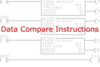
In this animated object, learners examine three data compare instructions used by programmable logic controllers (PLCs). A practical application to show how these instructions are used in an industrial setting is provided.
How Switches Increase Speed
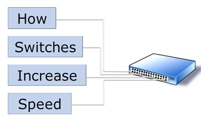
In this learning activity you'll observe how switches are used in local area networks to increase data transmission speeds.
Statistical Data Types
Learners read about the different uses of the word "data." They will test themselves on examples of data that is singular, plural, qualitative, quantitative, nominal, ordinal, interval, rational, discrete, or continuous.
Transfer Functions: The RC High Pass Filter with Bode Plot

Students view the development of the transfer function for a RC high pass filter. They also read how a Bode plot is developed through simple approximation techniques for both the magnitude and phase.
Data Flow on the Internet

In this learning activity you'll examine how a data file is broken into packets and transmitted over the Internet.
By Mark Puig
Line Graphs

Learners read an explanation of line graphs and demonstrate their knowledge of the parts of a graph in an interactive exercise.
The Transfer Functions: RC Low-Pass Filter with a Bode Plot

Students read how the transfer function is developed for an RC low-pass filter. A straight line Bode plot is drawn through close approximations.
Transfer Functions: The RL High Pass Filter (Screencast)

Learners read how the RL high pass filter is developed. The transfer function is used in Excel to graph the Vout. The circuit is also simulated in Electronic WorkBench and the resulting Bode plot is compared to the graph from Excel.
The Multiplexer/Demultiplexer IC Data Transfer Circuit

In this animated activity, the learner examines how a 74150 IC multiplexer and a 74154 IC demultiplexer work together when their data select lines are connected to the same input devices.
Transfer Functions: The RL Low Pass Filter

Learners read how the transfer function for a RC low pass filter is developed. The transfer function is used in Excel to graph the Vout. The circuit is also simulated in Electronic WorkBench and the resulting Bode plot is compared to the graph from Excel.
Transfer Functions: The RC High Pass Filter

Learners read how the transfer function for a RC high pass filter is developed. The transfer function is used in Excel to graph the Vout. The circuit is also simulated in Electronic WorkBench and the resulting Bode plot is compared to the graph from Excel.
Transfer Functions: The RC Low Pass Filter

Students read how the transfer function for a RC low pass filter is developed. The transfer function is used in Excel to graph the Vout. The circuit is also simulated in Electronic WorkBench and the resulting Bode plot is compared to the graph from Excel.
The Relationship of Data File Addresses to I/O Modules
In this animated learning object, students examine the addresses of PLC elements and how they pertain to I/O connections and internal memory files.
Test Your Business Etiquette
Learners consider a variety of business etiquette situations and determine if the response given is appropriate or inappropriate.