I am looking for: Learn arrow down
I am looking for:
Categories
Categories
Series RL Circuit Practice Problems
Students calculate current, phase angle, resistor voltage, inductor voltage, and power.
Transfer Functions: The RL High Pass Filter (Screencast)

Learners read how the RL high pass filter is developed. The transfer function is used in Excel to graph the Vout. The circuit is also simulated in Electronic WorkBench and the resulting Bode plot is compared to the graph from Excel.
Vector Diagram for a Series RL Circuit
Learners view a vector diagram for a series RL circuit. Information on the voltage across each component, the total voltage, and the phase angle is included.
Vector Diagram for a Parallel RL Circuit
Learners read about the vector diagram for a parallel RL circuit. This animated lesson presents information on current flow through each branch, total current, and phase angle.
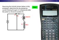
Instantaneous Current Calculations of a De-Energizing RL Circuit (Using a TI-36X Calculator)
Students view a sample of the keystrokes used on a TI-36X calculator to solve for the instantaneous current of a de-energizing circuit.
De-Energizing Time Constants of an RL Circuit
In this animated learning object, students examine current, voltage, and the magnetic field strength of a series RL circuit while it is de-energizing during five time constants. A quiz completes the activity.
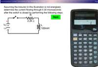
Instantaneous Current Calculations of a De-Energizing RL Circuit (Using a TI-30XIIS Calculator)
Students view a sample of the keystrokes of a TI-30XIIS calculator that are required to solve for the instantaneous current of a de-energizing circuit.
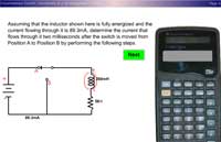
Instantaneous Current Calculations of an Energizing RL Circuit (Using a TI-36X Calculator)
Learners view a sample of the keystrokes on a TI-36X calculator that are required to solve for the instantaneous current of an energizing RL circuit.
Instantaneous Current Calculations of an Energizing RL Circuit (Calculator TI-30XIIS)
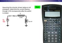
Students view the keystrokes of a TI-30XIIS calculator that are required to solve for the instantaneous current of an energizing RL circuit.
Transfer Functions: The RL Low Pass Filter

Learners read how the transfer function for a RC low pass filter is developed. The transfer function is used in Excel to graph the Vout. The circuit is also simulated in Electronic WorkBench and the resulting Bode plot is compared to the graph from Excel.
Energizing Time Constants of an RL Circuit

In this animated object, students view an explanation of how current, voltage, and the magnetic field strength of a series RL circuit change during five time constants. A brief quiz completes the activity.
The Ideal Bode Plot
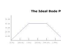
The Ideal Bode plot is introduced. The three main topics covered are: corner frequencies, midband voltage gain, and the roll-off rate.
Electronic WorkBench: The Bode Plotter

Electronic WorkBench has a virtual instrument called "The Bode Plotter." Students view the proper set-up and use of this device.
Families Around the World - Life Expectancy

In this learning activity you'll test your knowledge of global rates for life expectancy.
Time and Punctuality Around the World

Students view a world map and click on a country or continent to read about how the people there view time. A brief quiz concludes the activity.
Chickens Around the World

In this learning activity you'll explore how different cultures cook chicken in a variety of traditional dishes.
Dietary Manager Training: Hydration, Dehydration, and Elderly Clients

Learners read about the role of water, the basic physiology of water balance, and the effects of dehydration particularly on elderly clients. Tips for maintaining proper hydration are presented. In an interactive exercise, students calculate how much fluid a client needs based on his/her age, health, and weight.
Sizing Motor Overloads
Learners use the National Electrical Code to determine the size of a motor overload protection device.
World's Smallest Countries

Learners read about the five smallest countries in the world: The Vatican, Monaco, Naru, San Marino and Liechtenstein. A brief quiz completes the activity.
Series RL Circuit Vector and Circuit Analyzer
Learners alter circuit variables and view how these changes affect circuit voltage, current, reactance, impedance, and phase angle.