I am looking for: Learn arrow down
I am looking for:
Categories
Categories
RC Time Constant

In this animated object, learners observe the voltage on a capacitor at various time constants when it either charges or discharges. Students then answer questions in the categories of Identify, Compare, and Compute.
Listening Practice
This activity is cognitive. Learners will actively listen to a story activated by the computer. Then learners will take a quiz on their comprehension. Lastly, learners will compare their chosen answers against the answer key to determine how well they really did "actively" listen. (Credit given to Tom E. Wirkus, University Of Wisconsin-LaCrosse for this activity.)
Transfer Functions: The RL High Pass Filter (Screencast)

Learners read how the RL high pass filter is developed. The transfer function is used in Excel to graph the Vout. The circuit is also simulated in Electronic WorkBench and the resulting Bode plot is compared to the graph from Excel.
Pressure Measurement Scales (Screencast)
Learners compare the three scales used in pressure measurements: gage, absolute, and vacuum. A brief quiz completes the activity.
The Magnetic Circuit

Learners compare electromagnetic quantities with the voltage, current, and resistance quantities of an electrical circuit. A brief quiz completes the object.
Complex Numbers: So What's All the Fuss About?
Learners explore the use of complex numbers through a series AC circuit analysis problem. The steps are compared to the graphical method of finding circuit impedance and the phase angle.
Listening on the Job
Learners compare the behaviors and situations that interfere with listening on the job with those that enhance listening skills and job performance.
What I Want Now....The Hidden Costs of Rent-to-Own

In this learning activity you'll analyze the costs of rent-to-own buying plans and compare those plans to other consumer strategies.
Blog Etiquette in the Educational System

Learners examine the do's and don'ts of blogging in a school setting. They compare the features of a student blog with those of a classroom community blog. This learning object is particularly designed for instructors.
By Dean Lodes
Communicating in the Workplace

Compare the behaviors and situations that interfere with effective communication in the workplace with those that enhance listening skills and career performance.
Capacitor/Inductor: An Auto Analogy

Learners compare the experience of driving an auto to the circuit responses of RL (resistance/inductance) circuits and RC (resistance/capacitance) circuits. Acceleration, position, speed, and torque are graphed.
By Roger Brown
Data Compare Instructions
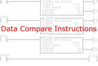
In this animated object, learners examine three data compare instructions used by programmable logic controllers (PLCs). A practical application to show how these instructions are used in an industrial setting is provided.
Assumptions vs. Facts
Learners read the definitions of an assumption and a fact. They then provide their own examples of each and compare those to the examples provided.
Op Amp Fundamentals: The Operational Amplifier
Students read about the characteristics of the ideal operational amplifier and compare them with the industry standard LM741C.
Characteristics of the TTL Series
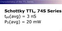
Learners read the characteristics of the TTL series. Examples are given and subfamilies are compared.
Comparing Analog and Digital Signals
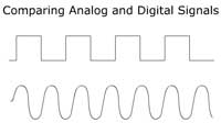
Learners compare animations of analog and digital data signals. A short quiz completes the activity.
Transfer Functions: The RL High Pass Filter With Bode Plot

Learners read how the transfer function for a RL high pass filter is developed. The transfer function is used in Excel to graph the Vout. The circuit is also simulated in Electronic WorkBench, and the resulting Bode plot is compared to the graph from Excel.
Transfer Functions: The RL Low Pass Filter

Learners read how the transfer function for a RC low pass filter is developed. The transfer function is used in Excel to graph the Vout. The circuit is also simulated in Electronic WorkBench and the resulting Bode plot is compared to the graph from Excel.
Transfer Functions: The RC Low Pass Filter

Students read how the transfer function for a RC low pass filter is developed. The transfer function is used in Excel to graph the Vout. The circuit is also simulated in Electronic WorkBench and the resulting Bode plot is compared to the graph from Excel.
Transfer Functions: The RC High Pass Filter

Learners read how the transfer function for a RC high pass filter is developed. The transfer function is used in Excel to graph the Vout. The circuit is also simulated in Electronic WorkBench and the resulting Bode plot is compared to the graph from Excel.