I am looking for: Learn arrow down
I am looking for:
Categories
Categories
Cardiac Marker Case Studies

The learner will learn how to understand, interpret, and correlate cardiac marker test results.
Cardiac Markers
Learners will examine how cardiac markers are used in the diagnosis of cardiac disease.
Scientific Notation - Converting Numbers Larger Than 1 to Scientific Notation (Screencast)
In this learning activity you'll review scientific notation and practice expressing numbers larger than 1.
The Mole and Avogadro's Number
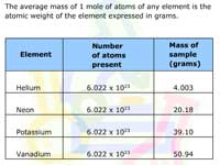
Learners examine how chemists use moles to "count" atoms by weight. Examples are given.
By Debbie McClinton Dr. Miriam Douglass Dr. Martin McClinton
Line Symbols (Screencast)
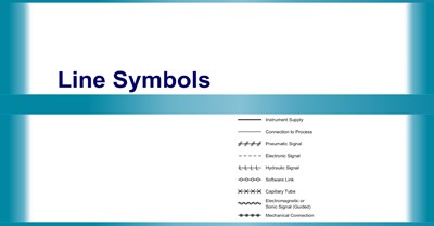
Learners examine the different types of lines used on a P&ID diagram and the types of connections they represent. They test their knowledge in a matching exercise.
Multiplication of a String of Signed Numbers
Students read how to organize their work when multiplying more than two signed numbers. A review and practice problems complete the activity.
By Mona Wenrich
Combined Variation
Superposition Theorem with Complex Numbers
Students read an explanation of "superposition" as a technique for ac circuit analysis. Complex numbers are used.
The Reynolds Number
In this animated learning object, users study the factors that affect a pipe’s fluid flow and how those factors pertain to a numerical value (the Reynolds Number).
The TI-83 Plus Calculator: Complex Number Conversion
Learners examine how to convert numbers from rectangular to polar form and from polar to rectangular form using a TI-83 Plus calculator.
An Algorithm for Converting a Decimal Number to an Octal Number
In this animated object, learners examine a systematic method for converting a decimal number (base 10) into an octal number (base 8).
Construction of the Cell Membrane
In this learning activity you'll study the structure of the cell membrane and construct it using the correct molecules.
By Becky Polk-Pohlman Barbara Liang
Multiplying and Dividing Signed Numbers
Students read the rules used in multiplying and dividing signed numbers. They view examples and work practice problems.
By Mona Wenrich
Costs and Benefits of Taxing to Pay for Lambeau Field
In this learning activity you'll apply cost-benefit economics to a real world public taxation issue.
By Mary Ascher
Using a Lumber Rule
Learners read how to use a lumber rule to quickly and accurately estimate board feet. They then use virtual samples to practice the process.
Ladder Logic Schematic Symbol Flashcards
This interactive object is designed to help learners memorize the schematic symbols used in ladder logic diagrams. Learners quiz themselves using electronic flashcards.
All Is Vanity: An Ambiguous Figure
In this learning activity you'll discover how your visual perception influences your understanding of ambiguous figures.
By Carol May
Electrical Units, Abbreviations, and Symbols
In this learning activity you'll read introduction to electrical quantities, units, and symbols and test their knowledge in a matching exercise.
Subtracting Mixed Number Fractions with Borrowing
In this learning activity you'll perform subtraction calculations using borrowing with mixed number fractions.
By Pat Walker
The TI-86 Scientific Calculator: Using Complex Numbers
This primer introduces the student to the correct method of entering complex numbers into a TI-86 calculator.